I've been toying with a switched phased array antenna design for use on a small aircraft. This type of antenna could be made to radiate forward, backward, or to the sides. With the addition of a Raspberry Pi Zero (or Arduino Teensie https://www.aeronetworks.ca/2016/08/minimalist-arduino-gps-parser.html), a UBlox GPS receiver and 4 little RF switches, your toy aircraft could then always point its antenna towards your ground control system, without using any step motors or moving parts - well, except for the armatures of the little RF switches.

The design is essentially four Yagi antennas positioned back to back in a cross. Only one dipole is driven at any time and the result is that the rearward parasitic elements act as a reflector for the antenna that is active. This improves the front to back ratio quite noticeably. The NEC2 graphs show extremely small back and side lobes, which I found so encouraging, that I went ahead and built the antenna to see whether it is indeed true.
The whole assembly could be housed inside a streamlined toadstool radome, the head about 190 mm in diameter and the stem about 150 mm high, with the RF switches in the bottom of the stem.
I aimed for about 10 dBi gain, which should result in about 8 dBi in reality. I don't want to make the gain too high, since then the 45 degree positions will be nulls. I did however leave room for yet another set of directors on the prototype antenna base, to gain another dB if needed.
With a directional antenna, it is not just the forward gain that is important, but the back and the side lobes need to be small, since the lobes introduce unwanted noise. The aim is to get an improved Signal to Noise Ratio, so that the aircraft radio will work better in both transmit and receive modes. The NEC2 prediction shows very small unwanted lobes and I hope I can achieve that in practice.

I modelled it in NEC2 and because of the large number of wire elements, I added tiny parasitic capacitors with LD cards to the ends of each wire, to make the simulation more accurate.


Now, I need to mount it on a wooden dowel post and measure the gain, to see how reality compares with the NEC2 predictions. The impedance and VSWR bumps were a concern and a couple of small ferrite beads over the cable quietened it down. Large beads will detune the antenna since everything is so close together - keep them small.


To measure the antenna, I needed to make yet another little Yagi to use as a receiver, which took a while to do and measuring an antenna in the open, without an anechoic chamber is very difficult. A 5 mm wooden dowel, a few more paper clips and O'l Bob's yer Uncle.

The little Yagi is the same as the phased array with a half folded dipole and a couple of ferrite beads to prevent current flowing down the co-ax screen, causing weird pattern effects and a bad VSWR. I left room in front on the boom for another director to up the gain by another dB if I would want to, but it worked well enough as is. I later cut the unused wooden snout off for aesthetic reasons.
You almost should not breathe while taking measurements indoors and the numbers are always rolling up and down for no apparent reason, due to reflections off the surroundings. The sun is also a strong C-band noise source and I live next to a couple of cell towers with C-band back-haul - all extremely non-ideal and going outside is therefore just as dreadful as inside. If you can't make any sense of your measurements, then you should probably add a few more ferrite beads on your cables. Otherwise you can try absorbent paint in your workshop - it should help a bit - or go and stand in the middle of a sports field or in a farmer's meadow:
https://www.mgchemicals.com/products/emi-and-rfi-shielding/water-based-conductive-coatings-wb-series/
Some more rough measurements in my living room indicates that the antenna more or less works as it is supposed to and I get in the order of 10 dB difference between the front to side and front to back, which is what I was hoping to achieve. This proves the concept, so the next step is to make the widget from FR-1 PCB to get the design more stable and repeatable. For this, I bought me a PCB milling machine for the princely sum of 285 Dirhams ($80!) - my next toy. Milling a board costs as much as Ferric Chloride and UV chemicals, but is less dangerous I think (I've etched boards and printed B&W photos when I was young and reckless).
For switching between the dipole elements, four little RF relays should work. At 5 GHz, one should use a miniature coaxial relay. A low cost reed relay will leak so much that it will upset the antenna pattern and VSWR. You really should invest in something with isolation of around 40 dB or better (about $80 to $120 each!), but be careful when you select one, since there appears to be little correlation between price and quality: https://eu.mouser.com/Electromechanical/Relays/High-Frequency-RF-Relays/_/N-5g33?keyword=5GHZ.
It is strange that FR-1 is hard to get these days, but it is making a comeback due to PCB milling machines (the router bits are blunted by glass fibre board, so old fashioned Bakelite is better).
https://www.amazon.ae/DealMux-7X10cm-Single-Laminate-Circuit/dp/B07T35QXWN/ref=sr_1_1?keywords=copper+fr1+pcb&qid=1582713898&sr=8-1
For this kind of antenna, I want a substrate with low permittivity and FR-1 is about 2, whereas FR-4 is about 3.5. FR-1 also has the advantage that it doesn't cover your workshop with white itch powder when you cut and drill it like FR-4 glass dust!
PCB Milling
I bought a small PCB Milling Machine and made a couple of test cuts. This one was done with a 0.8 mm high speed steel end mill, 0.15 mm deep, at 20 mm/minute, which took about 3 hours. The picture is fresh off the machine, I did not sand the board - just washed the oil off - there are no burrs. (On the Log Periodic Antenna experiments I tried 30 mm/min with 3 in 1 oil and got some burrs. Therefore 20 to 25 mm/min seems to be best with this little router, but I'm also wondering whether Diesel will make a bettter cutting fluid - 3 in 1 oil is SAE20 and may be lubricating too well).

This shows that it is possible to make prototypes this way and while it feels very slow, it is much faster than ordering boards from China. There are tiny flecks of copper foil left over here and there to scratch off with a blade. I have to increase the milling overlap a little for the next try.
Measurements
I connected the centre of the coax to the end of the J and the screen to the centre of the reflector.

The result is an almost perfect 49 Ohm match and the centre frequency is 5.056 GHz with a bandwidth of 4%. Usually a Yagi bandwidth is < 2%, so the 4% bandwidth is very nice. The rule of thumb is that d/L must be between 0.01 and 0.04. For the next one, I'll increase the rod diameter form 1 mm to 3 mm and see whether that makes a useful difference.
I designed for 4.75 GHz and then made a drawing with Inkscape - what you build is always different and will require tweaking to get it spot on. Usually the frequency goes down, not up, but who am I to argue...

This shows that PCB milling of common FR4 is a perfectly valid way to make a microwave antenna, but to repeatably get the frequency exactly where you want it, would either require precision high frequency substrates, or a way to trim the dipole length (make it a little too long, so you can trim it), or a small tuning circuit, or adjust the drawing and mill a new one. It depends on your time vs budget!


As you can see in the above plots, a Yagi antenna is a narrow band device. If you need a wide band array, then consider using a small log-periodic antenna https://hamwaves.com/lpda/en/index.html
Note that an antenna like this, can be scaled to any frequency, so you could make one for use at 2.4 GHz for example, but at 900 MHz it will be large and probably impractical for a small aircraft. It could be good for a ground station tracking antenna with no moving parts. You could also install 4 antennas on four ends of the aircraft, but beware of the coaxial cable losses.

Phased Array NEC2 Simulation
The design is essentially four Yagi antennas positioned back to back in a cross. Only one dipole is driven at any time and the result is that the rearward parasitic elements act as a reflector for the antenna that is active. This improves the front to back ratio quite noticeably. The NEC2 graphs show extremely small back and side lobes, which I found so encouraging, that I went ahead and built the antenna to see whether it is indeed true.
The whole assembly could be housed inside a streamlined toadstool radome, the head about 190 mm in diameter and the stem about 150 mm high, with the RF switches in the bottom of the stem.
I aimed for about 10 dBi gain, which should result in about 8 dBi in reality. I don't want to make the gain too high, since then the 45 degree positions will be nulls. I did however leave room for yet another set of directors on the prototype antenna base, to gain another dB if needed.
With a directional antenna, it is not just the forward gain that is important, but the back and the side lobes need to be small, since the lobes introduce unwanted noise. The aim is to get an improved Signal to Noise Ratio, so that the aircraft radio will work better in both transmit and receive modes. The NEC2 prediction shows very small unwanted lobes and I hope I can achieve that in practice.

Phased Array 5GHz Design
I modelled it in NEC2 and because of the large number of wire elements, I added tiny parasitic capacitors with LD cards to the ends of each wire, to make the simulation more accurate.

Phased Array 5GHz Wires and Loads
The prototype antenna elements are made from jumbo paper clips and the substrate is a piece of Lucite acrylic, so my antenna is transparent and the wires seem to float in the air. The pieces are held down with 'antenna putty' (UHU Patafix) - once tuned up, apply tiny drops of epoxy glue with a tooth pick.
The ultimate phased array was probably the enormous Soviet Duga Radar Antennas, which were built to detect incoming cruise missiles and which operated during the 1970s and 80s. It was abandoned when the Ukrainian site was contaminated by the Chernobyl accident, leaving a huge hole in the middle of the system, making it all useless. I remember as a teenager listening to their constant check-check-check screech on my shortwave receiver and wondering what on earth that horrid noise was. A Duga array used so much electricity, that it had to be next to a nuclear power station and is a bit too big for my backyard:

The wire elements of the array must be cut very carefully. You need to be within a fraction of a millimetre with each wire, otherwise the operating frequency will be off. The Lucite has a permittivity of 2, which is quite low. Alternatively use blank FR-1 phenolic paper (Bakelite) printed circuit board, which also has a permittivity of 2.
The magic of this design is in the bent wire element tips. Each wire end (3 mm) is bent slightly inwards. This makes the design more wide band and reduces the sensitivity of the antenna so that it doesn't get detuned by close objects so easily. Bending them is painful on the fingers - use small round nose pliers.
The ultimate phased array was probably the enormous Soviet Duga Radar Antennas, which were built to detect incoming cruise missiles and which operated during the 1970s and 80s. It was abandoned when the Ukrainian site was contaminated by the Chernobyl accident, leaving a huge hole in the middle of the system, making it all useless. I remember as a teenager listening to their constant check-check-check screech on my shortwave receiver and wondering what on earth that horrid noise was. A Duga array used so much electricity, that it had to be next to a nuclear power station and is a bit too big for my backyard:

Duga Radar Antennas
The wire elements of the array must be cut very carefully. You need to be within a fraction of a millimetre with each wire, otherwise the operating frequency will be off. The Lucite has a permittivity of 2, which is quite low. Alternatively use blank FR-1 phenolic paper (Bakelite) printed circuit board, which also has a permittivity of 2.
The magic of this design is in the bent wire element tips. Each wire end (3 mm) is bent slightly inwards. This makes the design more wide band and reduces the sensitivity of the antenna so that it doesn't get detuned by close objects so easily. Bending them is painful on the fingers - use small round nose pliers.

Phased Array 5 GHz Prototype
If you only need one or two of these toadstool antennas, then building it with little wires is quite practical, but if you want to make a million, then you should etch the elements on thin printed circuit board. Due to the thin dielectric on one side, the elements will then need to be slightly shorter, but the spacing will remain the same.
Initial measurements with a VNA looked encouraging, but some more work was needed to calm the antenna down - widen the band and improve the VSWR.
Initial measurements with a VNA looked encouraging, but some more work was needed to calm the antenna down - widen the band and improve the VSWR.

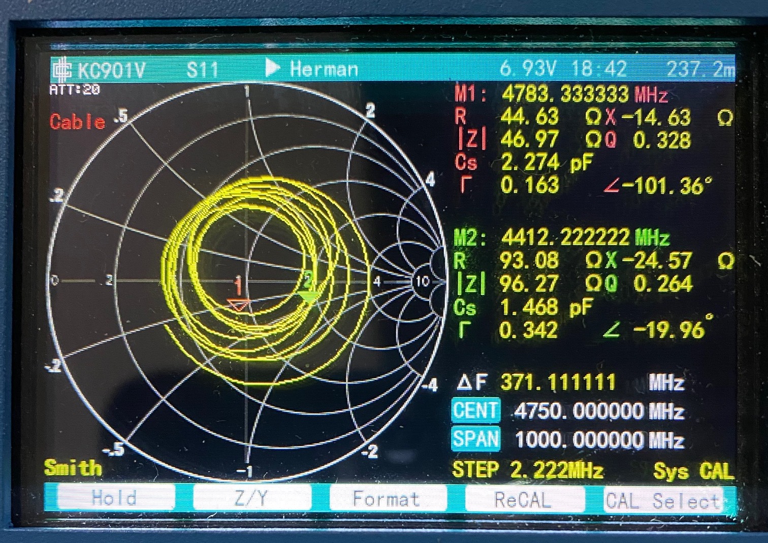
Phased Array 5GHz VSWR and Smith Chart
Now, I need to mount it on a wooden dowel post and measure the gain, to see how reality compares with the NEC2 predictions. The impedance and VSWR bumps were a concern and a couple of small ferrite beads over the cable quietened it down. Large beads will detune the antenna since everything is so close together - keep them small.

Ferrite Beads
The beads improved the matching significantly - still bumpy, but now the antenna is usable, with the VSWR below 2.

Improved VSWR with Ferrites
To measure the antenna, I needed to make yet another little Yagi to use as a receiver, which took a while to do and measuring an antenna in the open, without an anechoic chamber is very difficult. A 5 mm wooden dowel, a few more paper clips and O'l Bob's yer Uncle.

5 GHz Yagi
The little Yagi is the same as the phased array with a half folded dipole and a couple of ferrite beads to prevent current flowing down the co-ax screen, causing weird pattern effects and a bad VSWR. I left room in front on the boom for another director to up the gain by another dB if I would want to, but it worked well enough as is. I later cut the unused wooden snout off for aesthetic reasons.
You almost should not breathe while taking measurements indoors and the numbers are always rolling up and down for no apparent reason, due to reflections off the surroundings. The sun is also a strong C-band noise source and I live next to a couple of cell towers with C-band back-haul - all extremely non-ideal and going outside is therefore just as dreadful as inside. If you can't make any sense of your measurements, then you should probably add a few more ferrite beads on your cables. Otherwise you can try absorbent paint in your workshop - it should help a bit - or go and stand in the middle of a sports field or in a farmer's meadow:
https://www.mgchemicals.com/products/emi-and-rfi-shielding/water-based-conductive-coatings-wb-series/
Some more rough measurements in my living room indicates that the antenna more or less works as it is supposed to and I get in the order of 10 dB difference between the front to side and front to back, which is what I was hoping to achieve. This proves the concept, so the next step is to make the widget from FR-1 PCB to get the design more stable and repeatable. For this, I bought me a PCB milling machine for the princely sum of 285 Dirhams ($80!) - my next toy. Milling a board costs as much as Ferric Chloride and UV chemicals, but is less dangerous I think (I've etched boards and printed B&W photos when I was young and reckless).
For switching between the dipole elements, four little RF relays should work. At 5 GHz, one should use a miniature coaxial relay. A low cost reed relay will leak so much that it will upset the antenna pattern and VSWR. You really should invest in something with isolation of around 40 dB or better (about $80 to $120 each!), but be careful when you select one, since there appears to be little correlation between price and quality: https://eu.mouser.com/Electromechanical/Relays/High-Frequency-RF-Relays/_/N-5g33?keyword=5GHZ.
It is strange that FR-1 is hard to get these days, but it is making a comeback due to PCB milling machines (the router bits are blunted by glass fibre board, so old fashioned Bakelite is better).
https://www.amazon.ae/DealMux-7X10cm-Single-Laminate-Circuit/dp/B07T35QXWN/ref=sr_1_1?keywords=copper+fr1+pcb&qid=1582713898&sr=8-1
For this kind of antenna, I want a substrate with low permittivity and FR-1 is about 2, whereas FR-4 is about 3.5. FR-1 also has the advantage that it doesn't cover your workshop with white itch powder when you cut and drill it like FR-4 glass dust!
PCB Milling
I bought a small PCB Milling Machine and made a couple of test cuts. This one was done with a 0.8 mm high speed steel end mill, 0.15 mm deep, at 20 mm/minute, which took about 3 hours. The picture is fresh off the machine, I did not sand the board - just washed the oil off - there are no burrs. (On the Log Periodic Antenna experiments I tried 30 mm/min with 3 in 1 oil and got some burrs. Therefore 20 to 25 mm/min seems to be best with this little router, but I'm also wondering whether Diesel will make a bettter cutting fluid - 3 in 1 oil is SAE20 and may be lubricating too well).

5GHz Yagi Freshly Milled From FR4
This shows that it is possible to make prototypes this way and while it feels very slow, it is much faster than ordering boards from China. There are tiny flecks of copper foil left over here and there to scratch off with a blade. I have to increase the milling overlap a little for the next try.
Measurements
I connected the centre of the coax to the end of the J and the screen to the centre of the reflector.

5GHz Yagi on FR4
I designed for 4.75 GHz and then made a drawing with Inkscape - what you build is always different and will require tweaking to get it spot on. Usually the frequency goes down, not up, but who am I to argue...

5GHz Yagi Smith Chart
This shows that PCB milling of common FR4 is a perfectly valid way to make a microwave antenna, but to repeatably get the frequency exactly where you want it, would either require precision high frequency substrates, or a way to trim the dipole length (make it a little too long, so you can trim it), or a small tuning circuit, or adjust the drawing and mill a new one. It depends on your time vs budget!

5GHz Yagi VSWR

5GHz Yagi Return Loss
As you can see in the above plots, a Yagi antenna is a narrow band device. If you need a wide band array, then consider using a small log-periodic antenna https://hamwaves.com/lpda/en/index.html
Note that an antenna like this, can be scaled to any frequency, so you could make one for use at 2.4 GHz for example, but at 900 MHz it will be large and probably impractical for a small aircraft. It could be good for a ground station tracking antenna with no moving parts. You could also install 4 antennas on four ends of the aircraft, but beware of the coaxial cable losses.
Post Mortem
This Yagi idea works, but it is very narrow band. I consequently started work on a wide band log periodic antenna instead and it is rather more difficult to do.
Have fun!
Herman
Have fun!
Herman
Comments
Post a Comment
On topic comments are welcome. Junk will be deleted.