I reclined in the winter garten nursing my back and watched a gaggle of geese and aircraft soar overhead, which made me realize that it's been a while since I made an Air Traffic Control (ATC) antenna, so I dug in my Junque Bochs for an old Raspberry Pi v3, a RTL-SDR dongle and a tripod telescopic test antenna, downloaded the latest ADS-B (Automatic Dependent Surveillance-Broadcast) decoder image from https://www.adsbexchange.com/ and went to workplay.

The last time I worked with ADS-B transponders was maybe five years ago, when I used a RTL-SDR to test a Sagetech Mode-S ATC transponder and the free decoder software has improved dramatically since then. It took about an hour to set the system up and I could immediately see a handful of aircraft, as far away as 80 nautical miles (150 km), using a wonky little telescopic antenna on my office window sill.
After a while I captured an Emirates A380, a USAF Galaxy and a Slovak AF LET 410 Turbojet from the military airport nearby and I could see aircraft all the way to Vienna and Brno on my phone web browser - so how about aircraft around Prague?
To make a (hopefully!) better antenna, I broke out the O'l Slide Rule and calculated a quarter wavelength of 1090 MHz using λ x f = c, and λ = c / f, with c = 299792458 m/s.
Therefore an ideal quarter wave whip needs to be 68.8 mm long, or that is what the comictext books would want you to believe.
In practice an antenna is always shorter than the ideal, due to coupling to the environment, and the antenna support system - usually about 3% shorter.

If you want your antenna to be spot on, you need a Vector Network Analyzer (VNA), so you can clip little pieces off the driven element, till the center frequency is exactly where you want it to be. If you don't have a VNA, then you need to build five or ten antennas, each 1 mm shorter than the previous and then try them all and see which one works best, but to measure is to know!
With the help of my trusty Chinese VNA, I eventually found that the element length should be 62.5 mm, which is a good 10% shorter than the calculated ideal!
To make the antenna base, I cut a little wheel of fibreglass PCB with a hole saw and mounted it on a tripod with a piece of rigid strapping (a holy metal strip usually used to tie roof rafters together, but which is great for making ad hoc brackets, since it has an endless number of mounting holes at the ready).
The antenna elements were made from 18 SWG (1 mm) tinned copper wire (or five unrolled paper clips!), which is easy to work with.
The whip is soldered to the tip of a RG316/U coax, with the shield soldered to the copper board and the tip pointing up through the middle of the hole. I glued it in place with epoxy.
To make an earth plane, I soldered four quarter wave wires to the base PCB and bent them down - if you keep the earth plane flat, then the antenna will be very narrow band and difficult to tune.

Bending the wires down, makes the earth plane fade away towards the horizon, which makes the antenna much more calm and open minded. This bandwidth widening effect is amazing to see on a VNA - about 45 degrees seem to be optimal. I also added a couple of ferrite beads to the wire, but found that they don't have any effect - the bent earth plane wires dominate.
To tune the antenna, I let the VNA run and snipped tiny 1 mm pieces off the tip of the whip, until the VSWR dip was near enough to 1090 MHz. To tune an antenna, only adjust the driven element, leave the other metal parts alone.

The final tuned up antenna presented a VSWR of 1.1 and an impedance of 48 Ohm at 1090 MHz, which is a pretty good match to a 50 Ohm coaxial cable.
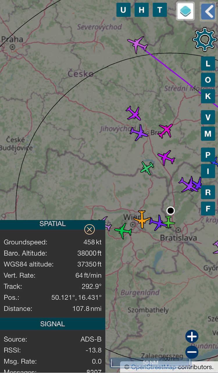
With the new finely tuned antenna sitting on my window sill, I can see about twice as many aircraft, up to about 108 nautical miles (200 km) away.
If you can mount an antenna outdoors, then it will work much better, but that is too much effort for me. I'll just leave it in the window.
I think this antenna build should be quite repeatable - the downward bent reflector wires make the bandwidth wide enough that it should work very well, even if your build is off by 50 MHz this way or that.
If you would add a 15dB Low Noise Amplifier to it, then you will get signals from 400 km or more, with too many aircraft to see on a phone. A little googling will find little ready built pre-amplifiers specially made for ADS-B, with an integral SAW filter to reduce interference, but I don't think I'm going to bother, since my tuned-up antenna is good enough.
It would be best to build an antenna on top of a bulkhead mounted RF connector, but I buy RF jumper cables from Pasternack or Mouser for serious work and then when one end breaks off, I use the remainder for these kind of experiments, which usually reduces the cost of my hobby antennas to practically zero.
For the adventurous, here is an ADS-B patch antenna:
https://www.aeronetworks.ca/2023/09/rf-controlled-impedance-pcb.html
La Voila!
Herman
Comments
Post a Comment
On topic comments are welcome. Junk will be deleted.