I have a bunch of dinosaur era Magic Eye tubes which I got from the Tubes-Store in Chellyabinsk and was wondering what to do with these roughly 100 million year old little cathode ray bulbs. An audio VU meter with a microphone pickup could make a nice magical flickering display as I originally described here: An Angel Dancing On a Pin Head.

Audio VU Meter - The First Flickers
The example Rusky circuit works, but it needs much more gain to work with a microphone, instead of a direct hook-up to the preamplifier of a guitar amplifier and it needs a power supply of sorts. So, I dusted the old circuit off, hooked up a little triode as a preamplifier to drive the display tube and my prototype worked. Moving the resultant rat's nest from the breadboard into a proper display case was another matter though.
Eventually, I redesigned the whole circuit when I rebuilt it, and rewrote most of this article.
Note that at audio frequencies, any old tube will work. If you have a weird and wondrous looking UHF or microwave tube, go ahead and try it - it will probably work just fine at baseband audio frequencies and will make your project look snazzy.
The 6E1P / EM80 cathode ray tube is super simple, since the Target and Anode are connected together internally, so you don't have to. It operates at a rather high 250V:
- Pin 1: Gate
- Pin 2: Cathode
- Pins 4, 5: Heater
- Pin 7: Anode
- Pin 9: Screen
Viewed from the bottom pin side, the pins are numbered clock wise, starting at the gap on the right.
The 6N21B miniature dual triode valve pin-out is as follows:
- Pin 1: k1
- Pin 2: s
- Pin 3: g1
- Pin 4: a1
- Pin 5: h
- Pin 6: k2
- Pin 7: no pin
- Pin 8: g2
- Pin 9: a2
- Pin 10: h
Because the double triode is physically small, the operating voltage is lower than normal at 'only' 100V to 150V.
Since the little valve doesn't have a socket, I used a ferrite toroid as a heat insulating base for it.
For a little toy like this, a pair of huge transformers will increase the cost and their bulk will detract from the whole idea, so I made a simple direct mains powered supply - shocking, eh...
Valves are very forgiving. The voltages need not be exact. When they work, they work. I've never managed to blow up a valve. That would require special skill. Caps and resistors though...

Magic Eye Tube VU Meter Circuit
A Magic Eye tube is a tiny cathode ray tube as in old TV sets and requires a very high operating voltage. Rectified 230 V mains results in +335 VDC, which is bright enough, as you can see in the picture.
The miniature triode needs a much lower voltage, so I used a large Anode resistor of 470 kilohm. The triode output is envelope detected to create a 0 to -2V negative voltage to drive the display tube gate - any small signal diode will work - a 1N4148 works.
Note that when you build high voltage circuits, you should use big parts. A 1/4W resistor is rated at 50V only. A 2W resistor is rated at 500V, which will prevent smoke signals. Ditto for small ceramic capacitors - be careful where you put a 50V cap.
A single triode has a gain of around 50. That should work with a dynamic mic. If you use a condenser mic, then you may need more gain (if it doesn't have an internal transistor amp). The small 6N21B is a dual triode and a two stage amplifier will result in a gain of around 2000, which should work. (These dual triodes are the world's first integrated circuits!) However, with a gain of 2000, the amplifier may oscillate if you don't take care with the wiring. I use RG316 coaxial cable for everything when I play with valve amplifiers (including the heater wiring), to ensure that all signals are screened properly.
Even if you do take great care with the wiring, the dual triode may still howl its head off. An alternative is to use a small transistor as a pre-amplifier and use only half of the triode (ground all the unused elements). The idea of this circuit is to display some glassware and two tubes look nice, while three may be too much of a muchness, hence the transistor suggestion.
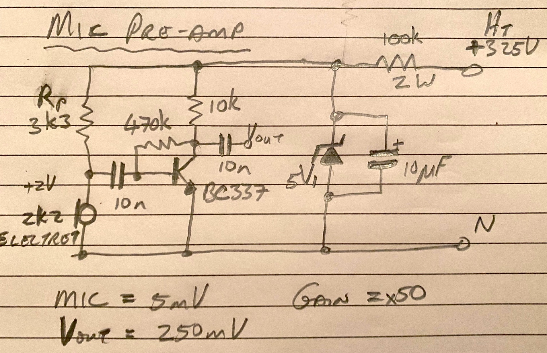
Microphone Preamplifier (Gain about x50)
With the above preamplifier (I used an ancient CAD program, called a pencil), you should have a signal that the triode can do something with, to get the needed 2 V at the envelope detector. Keep the coupling capacitors small, to suppress 50 Hz mains hum!
I have a couple of electret inserts, but they are so small, I could not find them! Rp provides phantom power for an electret - not needed for a dynamic microphone. Using a little CR-7 dynamic microphone insert, I measured 200 to 600 mV ptp when I whistle, which is very insensitive. A good 25 dBA electret will need much less amplification. So you got to tweak things to ensure that the resulting microphone level is good enough to drive the 6N21B valve amplifier for the VU meter.
Eventually, once the circuit started to work, I replaced the 10 nF capacitors with 100 nF, to improve the bass response and the 1M resistor in the envelope detector was replaced with 3M3 to make the decay time slower. You need to tweak it for a pleasant visual response.
The envelope detector works with a single diode, but you need two for a full wave rectifier. If you need more sensitivity, a couple of BAT42 Schottkey diodes will work better than a 1N4148 junction diode.
The heaters require about 350 mA (I have measured 280 to 370 mA) at 6.3 V. So for that, I made a simple capacitor ballast circuit using a 4u7 Safety Capacitor, which is rated to supply AC current continuously, in series with a 22 Ohm resistor to trim it to roughly 12 V and 300 mA.
For a fuse, I always use resettable polyfuses, since they don't blow permanently. For example Vishay PTCTL7MR100SBE, a 1A, 600V fuse. I always end up making mistakes and a resettable fuse is rather better than having to find a new glass fuse every time...
As with any thermionic valve circuit, this one is dangerously 'hot' and noisy. So when this toy is running, keep yer cotton picken fingers in yer pokkets - else you will be sorry. Mount the whole kaboodle in a plastic box for good insulation. I have a rubber mat on my shop floor - got zapped a few times and I'm still here...
La voila!
Herman
Do you have a 120 volt AC USA Version of this Schematic ?
ReplyDeletethank's
~ russ
Portland, Oregon. USA.
russramler@gmail.com
Just add another stage to each voltage doubler.
ReplyDelete