I am an ex Army Signals officer and also built military HF radio equipment for a period of about ten years - man pack, ground and airborne, so when I saw the new BitX40 radio kit, I just had to get a couple to play with.
These kits are made in India, are good quality surface mount, built up tested and aligned. For the princely sum of $59, one can get two or three and have fun:
http://www.hfsigs.com/

The BitX40 is an analogue radio, with a digital synthesizer tuner - so it is a throwback to some time before the dinosaurs, circa 1985 - nice and simple.
The default setup is for the 40 meter band, but one can tune it for any HF band, by using switches and coils. They are so cheap, one could get multiple radios and configure each for a different band of interest. However, given the current sun spot cycle, the 40 meter band is probably the best one.
Instead of an antenna, I hooked up a 50 Ohm wire wound resistor. Being a coil, it is actually not a good dummy load, but I always use one for radios and it works well enough. Another advantage of using resistors is that they leak enough that one can communicate over the air in a lab between two radios.
Once I'm sure the radio works properly, I'll build it into an instrument case, but knowing me, it will likely stay exactly like that for the next 6 months.
To keep the wiring up and away from the mother board, I'll add a little cable rack in the middle. It is important to make the box easy to open and close, since the BitX is designed to be experimented with.

The packaged radio now is about the same size as the Grinel TR178 HF Mini that I worked on many moons ago.

The toggle switches are on-off-momentary type. These are for PTT, Up, Down and Enter. The last three can be added to the Arduino software to navigate a menu of new features. Maybe I'll make it frequency hop one day - about 5 Hz hop rate would be fun and with a simple resynch on each PTT, it won't need temperature controlled, super stable clocks.
I cut the rectangle for the display with a Nibbling Tool. The trick for a pro finish is to slit open some 3 mm black heat shrink tubing and put it around the display cut-out edge at final assembly. All other holes are round and most were made with a Stepped Reamer. Two tools that are indispensable for a hobbyist!
In general, a series coil makes an antenna electrically longer and a series capacitor makes it shorter. Reactive components do not absorb energy - they don't get hot - and once a circuit is tuned and resonating merrily, it will radiate on the attached antenna wire.
Therefore, my next project will have to be a tuner, otherwise this little radio will never be usable. A L-match circuit can make a too short random wire/gutter/downspout/flagpole antenna resonate merrily:

The above is as simple as it gets. Instead of struggling to tune with complicated forward and reverse SWR power meter circuits on the radio side, simply tune for maximum smoke on the antenna side. Once in tune, real power is what you get, the imaginary components are gone and then a simple indicator works!
A 2 inch coil of 60 turns will have an inductance of about 120 uH and together with a 170 pF capacitor, it will resonate at about 1 MHz, so this tuner will work over the whole HF band.
For the coils, you can use a 2 inch air core coil former (also known as a chewing gum bottle), or a piece of ferrite - sticky tape and super glue (or the original contents of the bottle...) will also be handy. Once you have a few turns glued down, it becomes easier. Give super glue plenty time to dry or you will have wire wound finger tips instead of a coil. It is rather easier winding around ferrite and you'll use much less magnet wire.

If you like binary, then make the main coil with taps at 4, 8, 16, 32, 64 turns. If you like decimal then make it 10, 20, 30, 40, 50, 60, whatever floats your boat. For the LED, make some taps as well, so you can tweak the maximum brightness since it is dependent on the LED. If you manage to pop the LED, then your tuner really works.
The variable capacitor is available from various places that sell crystal radio kits (Mike's Electronic Parts) and then you'll get a ferrite bar also.

Toroids look fancy, but are painful to wind. Winding a coil or transformer around a bar is much easier and works just as well - if you look inside an old radio, you won't see any toroids. Sure, bars leak more RFI than toroids, but radiating is the whole purpose of an antenna, so in this case it really doesn't matter. Don't sweat about the design of a low power tuner - if it works, it works.
For a high power tuner, you need to pay attention to the high voltages and currents and use thicker, insulated wire and bigger ferrites, so then you need to do a few calculations to make sure it won't melt or arc.

To tune up, first set the cap to the middle, then adjust the coil for maximum noise on receive. Finally, press PTT, whistle into the mic (or use CW) and sweep the capacitor back and forth to find the range where the LED lights up and set it to the middle. That's all there is to it.
Note that the tuner needs to be at the base of the antenna, which is fine if your antenna is right next to, or on the roof of your radio shack. If your antenna is some distance away in the yard at the end of a long coax, then you need a remote controlled tuner. For that, you would need a more complex design with discrete coils, capacitors, a handful of relays and a little embedded processor.
The important point is that a tuner is always specific to a radio and an antenna. You will end up building one for each antenna project, so keep it simple. There is no point in making a complicated 'general purpose' tuner, since that is not how a tuner is used.
. -.-. .-. .- ... . --.. / .-.. .----. .. -. ..-. .- -- .
Nastravje,
Herman
These kits are made in India, are good quality surface mount, built up tested and aligned. For the princely sum of $59, one can get two or three and have fun:
http://www.hfsigs.com/
Bread and Circuses
Here is my breadboard setup. Yup, it is a real olde skool bread cutting board. Wood is a good insulator and some blue ticky-tacky keeps things down:
BitX40 7 MHz SSB HF Radio
The BitX40 is an analogue radio, with a digital synthesizer tuner - so it is a throwback to some time before the dinosaurs, circa 1985 - nice and simple.
The default setup is for the 40 meter band, but one can tune it for any HF band, by using switches and coils. They are so cheap, one could get multiple radios and configure each for a different band of interest. However, given the current sun spot cycle, the 40 meter band is probably the best one.
Instead of an antenna, I hooked up a 50 Ohm wire wound resistor. Being a coil, it is actually not a good dummy load, but I always use one for radios and it works well enough. Another advantage of using resistors is that they leak enough that one can communicate over the air in a lab between two radios.
Once I'm sure the radio works properly, I'll build it into an instrument case, but knowing me, it will likely stay exactly like that for the next 6 months.
Instrument Case
I dug up a little instrument case that I bought years ago, thinking that it will come in handy some day and it was a perfect fit. I just need to get a few more momentary switches and sockets from Electronic Surplus or similar junk shop.To keep the wiring up and away from the mother board, I'll add a little cable rack in the middle. It is important to make the box easy to open and close, since the BitX is designed to be experimented with.
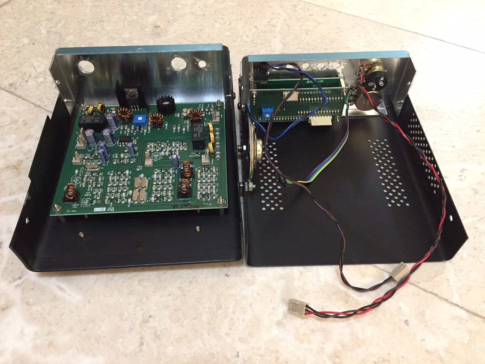
Insides
The packaged radio now is about the same size as the Grinel TR178 HF Mini that I worked on many moons ago.

Completed BitX40 HF Mini Transceiver
The toggle switches are on-off-momentary type. These are for PTT, Up, Down and Enter. The last three can be added to the Arduino software to navigate a menu of new features. Maybe I'll make it frequency hop one day - about 5 Hz hop rate would be fun and with a simple resynch on each PTT, it won't need temperature controlled, super stable clocks.
Tune-Up
A problem with a HF radio is of course the long antennas. The 40 meter band is called that for a reason and a quarter wave antenna needs to be 10 meters long. I am a firm believer in antenna tuners though. With a decent tuner, one can make any piece of metal resonate and these tuners need not be very complex - Grinel made a HF frequency hopping antenna that made a whole helicopter resonate.In general, a series coil makes an antenna electrically longer and a series capacitor makes it shorter. Reactive components do not absorb energy - they don't get hot - and once a circuit is tuned and resonating merrily, it will radiate on the attached antenna wire.
Therefore, my next project will have to be a tuner, otherwise this little radio will never be usable. A L-match circuit can make a too short random wire/gutter/downspout/flagpole antenna resonate merrily:

Maximum Smoke L-Tuner
The above is as simple as it gets. Instead of struggling to tune with complicated forward and reverse SWR power meter circuits on the radio side, simply tune for maximum smoke on the antenna side. Once in tune, real power is what you get, the imaginary components are gone and then a simple indicator works!
A 2 inch coil of 60 turns will have an inductance of about 120 uH and together with a 170 pF capacitor, it will resonate at about 1 MHz, so this tuner will work over the whole HF band.
For the coils, you can use a 2 inch air core coil former (also known as a chewing gum bottle), or a piece of ferrite - sticky tape and super glue (or the original contents of the bottle...) will also be handy. Once you have a few turns glued down, it becomes easier. Give super glue plenty time to dry or you will have wire wound finger tips instead of a coil. It is rather easier winding around ferrite and you'll use much less magnet wire.

Air Core Coil and Ferrite Toroid LED Transformer
If you like binary, then make the main coil with taps at 4, 8, 16, 32, 64 turns. If you like decimal then make it 10, 20, 30, 40, 50, 60, whatever floats your boat. For the LED, make some taps as well, so you can tweak the maximum brightness since it is dependent on the LED. If you manage to pop the LED, then your tuner really works.
The variable capacitor is available from various places that sell crystal radio kits (Mike's Electronic Parts) and then you'll get a ferrite bar also.

A ferrite bar makes a much more compact coil
Toroids look fancy, but are painful to wind. Winding a coil or transformer around a bar is much easier and works just as well - if you look inside an old radio, you won't see any toroids. Sure, bars leak more RFI than toroids, but radiating is the whole purpose of an antenna, so in this case it really doesn't matter. Don't sweat about the design of a low power tuner - if it works, it works.
For a high power tuner, you need to pay attention to the high voltages and currents and use thicker, insulated wire and bigger ferrites, so then you need to do a few calculations to make sure it won't melt or arc.

HF Low Power Antenna Tuner
To tune up, first set the cap to the middle, then adjust the coil for maximum noise on receive. Finally, press PTT, whistle into the mic (or use CW) and sweep the capacitor back and forth to find the range where the LED lights up and set it to the middle. That's all there is to it.
Note that the tuner needs to be at the base of the antenna, which is fine if your antenna is right next to, or on the roof of your radio shack. If your antenna is some distance away in the yard at the end of a long coax, then you need a remote controlled tuner. For that, you would need a more complex design with discrete coils, capacitors, a handful of relays and a little embedded processor.
The important point is that a tuner is always specific to a radio and an antenna. You will end up building one for each antenna project, so keep it simple. There is no point in making a complicated 'general purpose' tuner, since that is not how a tuner is used.
. -.-. .-. .- ... . --.. / .-.. .----. .. -. ..-. .- -- .
Nastravje,
Herman
Comments
Post a Comment
On topic comments are welcome. Junk will be deleted.